

The fully plastic moment of a section (Mp) is the maximum moment of resistance of a fully yielded cross-section. The yielded zone due to bending where infinite rotation can take place at a constant plastic moment (Mp) is called a plastic hinge.
In order to find the fully plastic moment of a yielded section, we normally employ the force equilibrium equation by saying that the total force in tension and compression at that section are equal. In frames, the plastic moment can be easily obtained using the kinematic method (upper bound theorem).
When a system of loads is applied to an elastic body, it will deform and show some resistance to deformation, and such a body is called a structure. On the other hand, if no resistance is set up against deformation, such as a body is said to have formed a mechanism. This can occur in structures such as beams and frames.
One of the fundamental conditions for plastic analysis of a framed structure is that the collapse load is reached when a mechanism is formed, in which the number of plastic hinges developed in the structure is sufficient to form a mechanism. The load factor (λ) at rigid plastic collapse is the lowest multiple of the design load which will cause the whole structure or part of it to form a mechanism.
It is important to realise that the number of independent mechanisms in a structure is related to the number of plastic hinge locations and the degree of redundancy of the system.
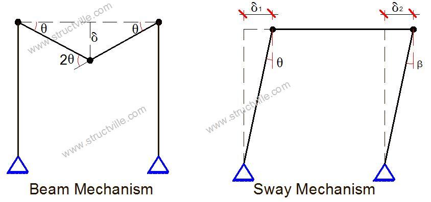
In beams, identification of critical spans in terms of Mp or load factor can be obtained using the static or kinematic method by considering simple beam mechanisms. But in framed structures, other types of mechanisms such as joint, sway, and gable mechanisms are also considered. Each of these mechanisms can occur independently, but it also possible for a critical collapse mechanism to develop by combination of the independent mechanisms.
The purpose of combining mechanisms is to eliminate hinges that exist in the independent mechanism leaving only the minimum number required in the resulting combination to induce collapse.
The steps in the plastic analysis of frame structures are as follows;
- Calculate the degree of static indeterminacy of the structure (RD)
- Calculate the number of possible plastic hinges (RD + 1)
- Identify the independent collapse mechanisms and evaluate them
- Combine the independent mechanism and eliminate hinges where applicable
- Obtain the critical plastic moment Mp which is the highest bending moment in the structure
- Check for equilibrium and evaluate the reactive forces
- Plot the final plastic moment diagram. No bending moment at any point in the structure should exceed the critical plastic moment.
Solved Example
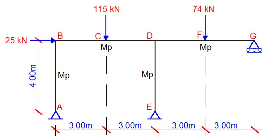
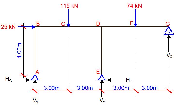
For the frame loaded as shown below, find the critical Mp value, and draw the collapse moment diagram. The loads are factored.
Degree of static indeterminacy
RD = (3m + r) – 3n
m (number of members) = 4
r (number of support reactions) = 5
n (number of nodes) = 5
RD = (3 × 4 + 5) – 3(5) = 2
Therefore the frame is indeterminate to the second order.
A little consideration will show that the possible places where we could have plastic hinges in the structure are at node B, section C, section D (just to the left), section D (just to the right), section D (below) and section F. Nodes A, E, and F are all natural hinges. Therefore, total number of possible hinges = 6
Hence, number of independent collapse mechanisms = 6 – 2 = 4
These independent mechanisms are listed below;
– 2 Beam mechanisms (span B – D and span D – G)
– 1 sway mechanism of the entire frame due to the horizontal load
– 1 joint mechanism
Analysis of the independent mechanisms
Mechanism 1
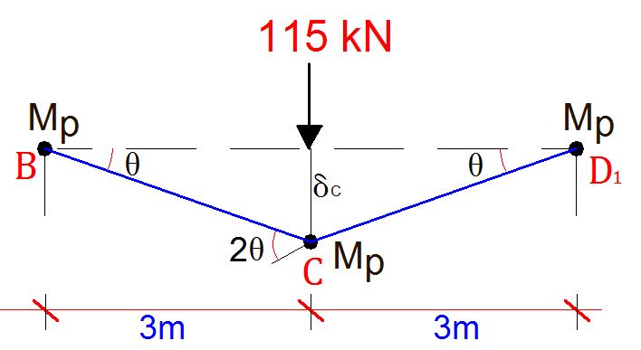
δC = 3 × θ = 3θ
Internal work done due to rotations at internal hinges at B, D, and C
Total internal work done (Wi) = Mpθ + Mpθ + 2Mpθ = 4Mpθ
External work done (We) = 115 × 3θ = 345θ
Let external work done = Internal work done
4Mpθ = 345θ
On solving, Mp = 345/4 = 86.25 kNm
Mechanism 2
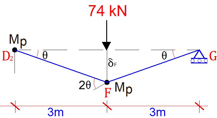
δF = 3 × θ = 3θ
Internal work done due to rotations at internal hinges at B, and F. No work is done at G because it is a natural hinge.
Total internal work done (Wi) = Mpθ + 2Mpθ = 3Mpθ
External work done (We) = 74 × 3θ = 222θ
Let external work done = Internal work done
3Mpθ = 222θ
On solving, Mp = 222/3 = 74 kNm
Mechanism 3 (Sway)
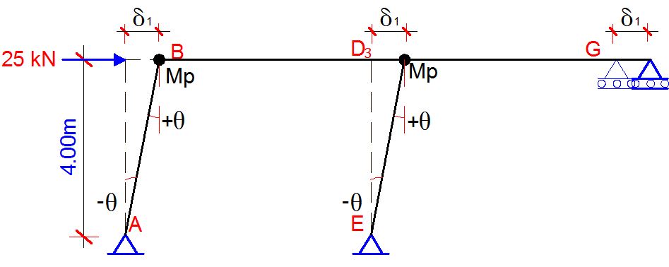
δ1 = 4 × θ = 4θ
Internal work done due to rotations at internal hinges at B, and D. No work is done at A, E, and G because they are all natural hinges.
Total internal work done (Wi) = Mpθ + Mpθ = 2Mpθ
External work done (We) = 25 × 4θ = 100θ
Let external work done = Internal work done
2Mpθ = 100θ
On solving, Mp = 100/2 = 50 kNm
Mechanism 4 (Joint Rotation)
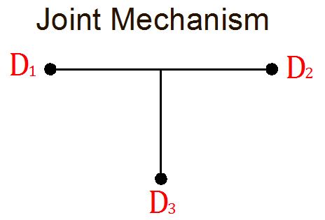
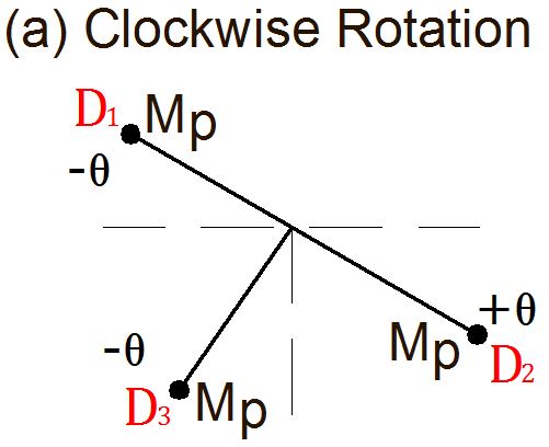
Internal work done = Mpθ + Mpθ + Mpθ = 3Mpθ
External work done = 0 (no external work done)
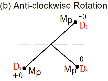
Internal work done = Mpθ + Mpθ + Mpθ = 3Mpθ
External work done = 0 (no external work done)
Let us now consider the possible mechanism combination by preparing the table below
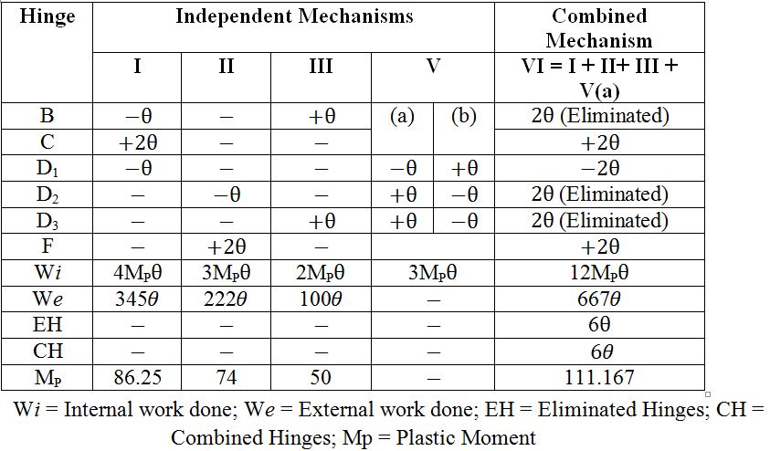
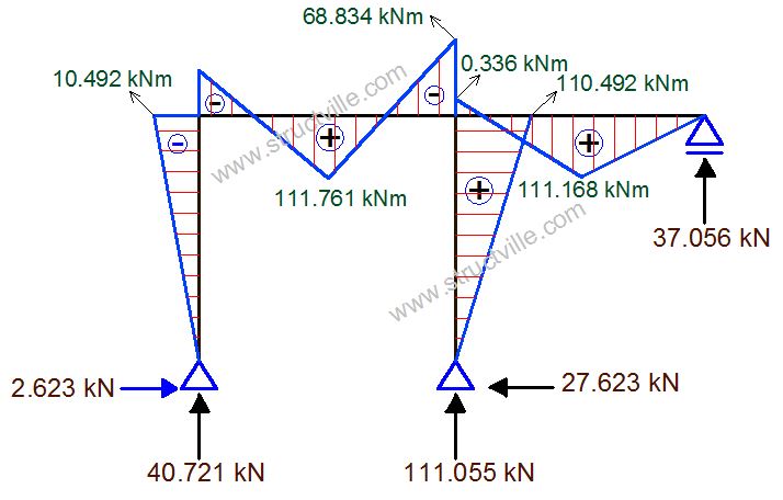
The critical Mp is therefore = 111.167 kNm (This was achieved after other combinations were considered but this was found to be the highest).
Note that by virtue of the combination, internal hinges at B, D2, and D3 were eliminated. So the critical collapse mechanism is as given below;
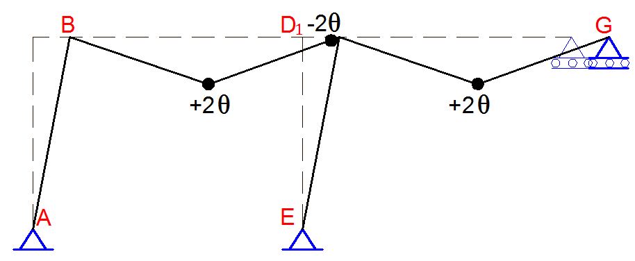
Note that the implication of our analysis above is that points C, F and D1 are plastic hinges, with a full plastic moment of 111.167 kNm. While C and F are sagging, D1 is hogging. No other bending moment in the structure should exceed this value. Once a higher moment is discovered, it means that the critical collapse moment was not appropriately obtained.
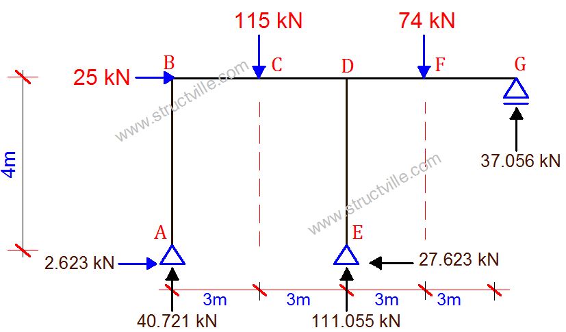
∑MFR = 0 (anti clockwise positive)
3VG = 111.167
VG = 37.056 kN
∑MCL = 0 (clockwise positive)
3VA – 4HA = 111.167 ———– (1)
∑MDL = 0 (clockwise positive)
6VA – 4HA – (115 × 3) = -111.67
6VA – 4HA = 233.833 ———– (2)
Solving (1) and (2) simultaneously;
VA = 40.721 kN
HA = 2.623 kN
∑MA = 0 (clockwise positive)
12VG + 6VE – (74 × 9) – (115 × 3) – (25 × 4) = 0
6VE = 666.328
VE = 111.055 kN
∑Fx = 0
HE = 25 + 2.623 = 27.623 kN
Bending Moment
You can verify that having obtained the support reactions, the bending moment diagram can easily be plotted without strenuous calculations.
Thank you for visiting Structville today, and God bless you.


wonderful post. its been a while. i want to ask, wat is d rational behind making theta positive or negative? is there a rule governing dat decision? again thank u very much fr enlightening me with such post. God bless u profusely.
wonderful post. its been a while. i want to ask, wat is d rational behind making theta positive or negative? is there a rule governing dat decision? again thank u very much fr enlightening me with such post. God bless u profusely.
Hi Ovie,
The rationale behind that is a matter of sign convention. You can likewise vary yours. For instance, you can call outward rotation positive, and inward rotation negative. You will arrive at the same answer provided you are consistent with the convention you adopted.
What do you mean by outward and inward rotation? Can you elaborate further?
any reference book i would deeply appreciate
hey, can someone explain the logic behind the sign convention used in sway mechanism?
In the case of the sway, shouldn’t all the rotations be positive? We need a reference to measure the rotations from? In this case, let’s say the original reference is the original vertical direction of the columns. One the structure sways, if our sign convention is that counterclockwise moments and rotations are positive, then all the rotations in mechanism 3, are negative, and if our sign convention is that clockwise rotations are positive, then all the rotations will be positive. Nevertheless, the answers for the products of the Mp and rotations in the application of the virtual moments Mp going through the virtual rotations will be positive, because the plastic moments have the same directions as the virtual rotations they go through.